Uniaxic interference figures and the orientation of the mineral cut
In uniaxial crystals, the interference figure is formed by an isogyre constituted by two black bands which intersect at right angles, forming a cross, and by various isochromatic curves represented by concentric circles with interference colours which are increasingly higher as they get towards the periphery of the field.
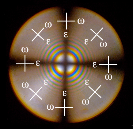
In order to find out whether a certain point in the figure belongs to the isogyre (extinction position) or to an isochromatic curve (general position) you only have to join the point in question to the centre of the cross; the extraordinary component (epsilon) will vibrate in the radial direction and the ordinary component (omega) will vibrate perpendicularly (tangent to the circle). If these coincide with the directions NS and EW, it means that they belong to the isogyre, as they coincide with the directions of vibration of the polariser and analyser. If they do not coincide, they must belong to an isochromatic curve.
The orientation of the mineral cut
The interference figures of uniaxial crystals vary according
to the cut of the mineral plate.
Principal orientations of the cut of the mineral plates
 a = cut perpendicular
to the optic axis
a = cut perpendicular
to the optic axis
b = cut inclined to the optic axis
c = cut very inclined to the optic axis
d = cut parallel to the plane of the optic axis
a. Cut perpendicular to the optic axis
The interference figure is formed by an isogyre constituted by two black bands which intersect at right angles, forming a cross, and by various isochromatic curves represented by concentric circles with interference colours which are increasingly higher as they get towards the periphery of the field.
The centre of the isogyre cross coincides with the centre of the microscope field.
![]()
When turned, no changes occur (it neither moves nor changes shape). This interference figure identifies it as a uniaxial mineral.
b.Cut inclined to the optic axis
The interference figure is formed by an isogyre constituted by two black bands which intersect at right angles, forming a cross, and by various isochromatic curves represented by concentric circles with interference colours which are increasingly higher as they get towards the periphery of the field.
The centre of the isogyre cross is displaced from the centre
of the field.
The more inclined the angle, the further the centre of the isogyre cross moves towards the periphery of the field (section "i" in the figure).
![]()
![]()
![]()
This interference figure identifies it as a uniaxial mineral.
c. Cut very inclined to the optic axis
The interference figure is formed by an isogyre cross whose centre is situated outside the field of view. As it is turned, the figure is seen in parts.
A single isogyre band is seen which moves about the field of view until it disappears altogether. Sometimes it is the vertical band of the isogyre cross that enters the field and sometimes the horizontal one does so.
![]()
Theoretically, a crystal can always be identified as uniaxial when the bands remain straight, and do not bend, when leaving the field. In practice, however, there can be some confusion, and it is preferable to look for other grains of the mineral with different cuts.
d. Cut parallel to the plane of the optic axis
When the cut is parallel to the optic axis (optical axes lie in to the plane of the section), a flash figure is formed, which is characterised by an isogyre cross made up of extraordinarily broad bands which occupy nearly the whole field of view. However, when the microscope stage is turned even slightly (<5°), it disappears completely.
![]()
The figure does not distinguish uniaxial and biaxial minerals.
Index | Introduction | PPL | XPL orthos | XPL conos | Previous | Next | Top