Consequences
of conoscopic illumination
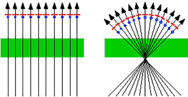
This very simplified diagram shows the effect produced by the microscope's condenser.

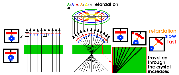
On the left hand side, without the condenser (orthoscopic illumination), the rays cross the mineral plate which is situated on the microscope stage, and continue in parallel lines. This means that they all behave in the same way. Double refraction is equal in all of them, i.e. same path, same phase difference between the two components, represented by "-"and ".", same directions of vibration for all the rays and same crystal orientation. The crystal will therefore have the same interference colour at all points.
On the other hand, the right hand side of the diagram shows what happens when the condenser is incorporated (conoscopic illumination). A series of concentric cones are produced with varying degrees of inclination, which converge exactly in the lower plane of the preparation. This converging light has two very important effects:
![]() The trajectory of the waves is different.
The trajectory of the waves is different.
![]() The directions of vibration of the waves are different.
The directions of vibration of the waves are different.
1 The trajectory of the waves is different
Indeed, as is shown in the diagram, as the rays become more inclined, the path travelled through the crystal increases proportionately and thus the phase difference between the fast and slow wave corresponding to each ray will also increase progressively, leading to respective changes in the interference colour.

Similarly, as the degree of inclination of the waves changes, the anisotropy of the crystal will also vary. The birefringence value of the crystal will be different for each cone of rays.
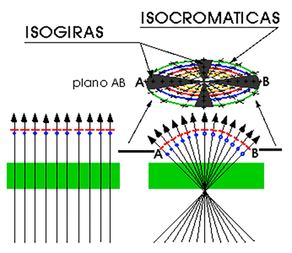
As a result of both these factors - birefringence and thickness - each cone of rays with the same degree of inclination will produce a particular interference colour which will be different to that presented by the other cones. Thus a series of concentric loops will appear with different interference colours which are known as isochromatic curves and can be defined as the geometry of all the rays with equal retardation.
2 The directions of vibration of the waves are different
As the degree of inclination of the rays varies with the converging light, it is evident that the direction of propagation also varies. As this varies, the direction of the fast and slow waves corresponding to each ray will also have to change, as both directions (propagation and vibration) can be considered as perpendicular.
Thus, there will be some rays which are in the general position (their directions of vibration do not coincide with those of the polariser and analyser) and these will show an interference colour which corresponds to their retardation, whilst there will be others in the extinction position (their directions of vibration coincide with those of the nicols) and thus they will be seen as black. This means that the isochromatic curves will be interrupted by some dark areas (see also the figure).

These dark areas are known as isogyres and together with the isochromatic curves constitute the two elements which make up the interference figure. The isogyres can be defined as the geometry of all the rays which are in the extinction position.
Index | Introduction | PPL | XPL orthos | XPL conos | Previous | Next | Top